Open Frame Suppression Filter System
Installation Instructions
Current Technology, Inc.
3001 W. Story Rd.
Irving, TX 75038
1. Mount unit securely and rigidly to the interior of the equipment to be protected. Pull wire as necessary to make three phase connections, the neutral connection (if applicable) and the ground connection. The unit is to be installed as close as possible to the bus structure of the equipment. Also minimize wire lengths and avoid unnecessary wire bends.
2. Install wiring as detailed below:
UNIT WITH STANDARD INTEGRAL FUSED DISCONNECT SWITCH
Units with integral fused disconnect may be directly to electrical system with #4 AWG COPPER conductors, or via a three-pole 35 amp breaker with #4 AWG COPPER conductors.
Neutral tap conductor should be at least 100% of Phase conductor ampacity (phase conductor used as connection to this unit).
1) Wire should be appropriately stripped for inserting into lugs.
2) Connect the three phase conductors into the top lugs of the disconnect switch with Phase A connected to lug labeled L1, Phase B connected to lug labeled L2, and Phase C connected to lug labeled L3.
3) Lugs should be appropriately tightened.
FOR DISTRIBUTION SYSTEMS WITH A GROUND AND/OR NEUTRAL CONDUCTOR, SEE BELOW
NEUTRAL INSTALLATION: Connect neutral tap conductor to lug marked “NEUTRAL TERMINAL”.
GROUND INSTALLATION: Connect ground tap conductor to green lug mounted in top center of enclosure labeled “SAFETY GROUND TERMINAL” and the copper lug mounted on the top left side of the unit’s “MERF” labeled “TRANSIENT GROUND”. The ground tap conductor should be tapped from the grounding plane derived from the service entrance connection.
Operating Handle Installation
Position hole pattern to allow operating rod to extend from the enclosure by at least one half of an inch so that it will extend into operating handle. Surface mount operating handle over the hole pattern to allow operating rod to contact operating handle appropriately. Adjust length of operating rod for best contact with operating handle.
Monitoring Panel Installation
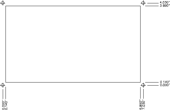
Mount monitoring panel on the face of the enclosure using the hole pattern shown below labeled Monitoring Panel Hole Pattern. Make connections to the suppression filter system using cable provided.

Monitoring Panel Hole Pattern
Monitoring Panel Driver Board Installation
The monitoring panel driver board should be mounted to the interior of the unit in a convenient position to allow for the connections from the suppression filter system and the monitoring panel. After mounting, use one of the included cables to connect from the plug-in Molex connector on the suppression filter system to the monitoring panel driver board, and the remaining cable to connect from the monitoring panel driver board to the monitoring panel face.
Wiring the Form “C” Dry Contacts
For wiring of the form “C” dry contacts, identify the three output terminals located on the monitor panel: common, normally open and normally closed. These output terminals are labeled C, NO and NC accordingly. For normally closed operation, connect the normally closed terminal and common terminal to the monitoring indicator. For normally open operation, connect the normally open terminal and common terminal to the monitoring indicator. When the status of the unit’s fuses/suppression elements changes, the NC and NO outputs reverse their status. Form “C” dry contacts are rated for 0.5 amps at 120 volts.
