Electrical Transient Suppression Filter Systems
Installation, Operation and Maintenance Instructions Generation II
MP, DP, DPA, SBA and BPA Models
INTRODUCTION
Congratulations on joining the extensive list of satisfied Current Technology customers. Since our inception in 1971, we have installed thousands of electrical transient suppression filter systems to protect critical loads in a wide variety of industries.
The success of Current Technology products is a result of more than two decades of focused lab and field research resulting in a unique and exclusive approach to mitigation of power anomalies. Our patented suppression filter systems provide all modes of bi-directional surge sifting and line noise filtering with a revolutionary engineering design called seamless technology .
Taking a unique and superior approach to the mitigation of power anomalies, seamless technology utilizes the individual performance capabilities of up to four major components — selenium cells, carbon thin film high energy capacitors, metal oxide varistors (MOVs), and synergistic component geometry — to deliver “seamless” power without damaging surges, flicker or HF noise.
Only Current Technology combines the four components of seamless technology for an orchestrated effect. Much like an orchestra, all four parts work together to produce results vastly superior to the efforts of one or two components.
To maximize performance from your Current Technology suppression filter system, strategic location is as important as correct wiring methods. Proper physical location will enable your unit to provide the industy’s most reliable transient and noise protection. Your Current Technology suppression filter system should be installed as close to the protected loads as possible; wire lengths and wiring bends should be minimized. This positioning maximizes both surge suppression and filtering, while providing added protection for the protected loads. Please contact our engineering department or your sales representative if you require additional information.
Today’s sophisticated electronic systems require the best power conditioning possible. By selecting Current Technology products, you have taken a critical step toward decreasing downtime and ensuring longer product life for your equipment. We look forward to fulfilling your suppression filter system needs.
INSTALLATION
THE FOLLOWING IS INTENDED FOR QUALIFIED ELECTRICAL PERSONNEL ONLY. READ COMPLETE INSTALLATION INSTRUCTIONS BEFORE BEGINNING INSTALLATION. CALL CURRENT TECHNOLOGY WITH ANY QUESTIONS. IT IS THE FINAL RESPONSIBILITY OF THE INSTALLING ELECTRICIAN TO ENSURE THAT ALL LOCAL CODES AND OTHER APPLICABLE SAFETY/ENVIRONMENTAL CONDITIONS ARE MET.
Enclosure/Environment: The standard enclosure for the CURRENT TECHNOLOGY MP, DP, DPA and SBA suppression filter system is a NEMA Type 1. (Other NEMA Type enclosures are available.) The standard enclosure for the BPA suppression filter system in a NEMA type 4/12. All units should be installed in a safe protected area with ambient temperature between -40oC to +60oC (-40oF to +140oF). Humidity should be 5-95% non-condensing relative humidity.
1. Verify Voltages: Ensure that ALL voltages are correct and verify the type of power distribution configuration used (i.e., 3 Phase 120/208 grounded WYE) before installation. See Tables 4 for nominal voltages and voltage configurations for each model. Product model number is found on the product label inside unit.
WARRANTY VOID IF CONNECTED TO IMPROPER VOLTAGE. CHECK SOURCE VOLTAGES BEFORE CONTINUING. CHECK NEUTRAL BOND AT DISTRIBUTION TRANSFORMER PROVIDING POWER TO PROTECTED LOADS AND NEUTRAL BOND AT SERVICE ENTRANCE TO VERIFY Xo BOND CONNECTION INTEGRITY.
CAUTION !
Units designed for power distribution systems utilizing a ground MUST NOT be installed on ungrounded distribution systems. Refer to Table 1 for configuration and nominal voltages for your particular model. For “high-leg” delta model with suffixes 120/240-3GHD, the “high-leg” MUST be connected to Phase B (middle phase lug).
2. Punch conduit holes for conduit connectors in gray shaded areas shown in Figures 1-5 so external wiring will not interfere with internal components nor require excessively sharp bends. Conduit fitting should be located near upper right of enclosure to allow easy connection to input lugs.
NOTE: Larger wire sizes may require top conduit entrance in order to meet wire bending requirements.
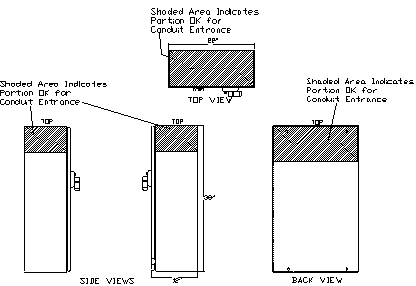
Figure 1.
MP CONDUIT ENTRANCE LOCATION
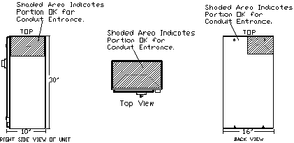
Figure 2.
DP CONDUIT ENTRANCE LOCATION
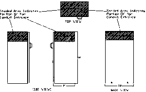
Figure 3.
SBA or DPA Surface Mount CONDUIT ENTRANCE LOCATION
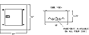
Figure 4.
DPA Flush Mount CONDUIT ENTRANCE LOCATION

Figure 5.
BPA CONDUIT ENTRANCE LOCATION
3. Mount unit securely and rigidly to building surface or structural member using 4 mounting holes provided on back wall of unit before electrical connection. Attach conduit and pull wire as necessary. Refer to Figures 6 – 9 below for mounting hole dimensions and spacings. The unit is to be installed as close as possible to the facilities’ wiring system to minimize wire lengths and avoid unnecessary wire bends.
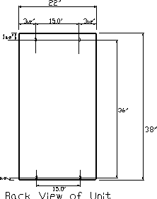
Figure 6.
MP MOUNTING TEMPLATE DRAWING
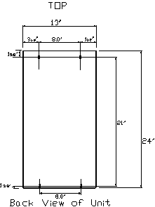
Figure 8.
SBA or DPA Surface Mount MOUNTING TEMPLATE DRAWING
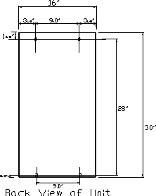
Figure 7.
DP MOUNTING TEMPLATE DRAWING

Figure 9.
BPA MOUNTING TEMPLATE DRAWING
4. Install wiring as detailed below:
A. UNITS WITH INTEGRAL FUSED DISCONNECT SWITCH
Units with optional integral fused disconnect may be installed as a Tap with COPPER conductors shown in Table 1 below (See notes 1 and 2), or via a three-pole 35 amp breaker with conductors as shown in Table 1 below (see notes 1 and 2).
| Unit | Recommended Conductor |
| MP | #2 AWG Copper |
| DP | #4 AWG Copper |
| SBA | #8 AWG Copper |
| DPA | #8 AWG Copper |
| BPA | #8 AWG Copper |
Table 1
Recommended Installation Conductor Chart
It is recommended that Neutral and Ground conductors connecting this unit should be at least 100% of Phase conductor ampacity.
1) Remove the plastic phase guard on the top of the disconnect switch to expose the phase lug screws (if applicable).
2) Wire should be appropriately stripped for inserting into lugs.
3) Connect the three phase conductors into the top lugs of the disconnect switch with Phase A connected to lug labeled L1, Phase B connected to lug labeled L2, and Phase C connected to lug labeled L3. See Figures 10-14. For single phase installations, Phase B/Lug L2 is not used.
4) Lugs should be appropriately tightened.
5) Replace th plastic phase guard on the top of the disconnect switch.
FOR DISTRIBUTION SYSTEMS WITH A GROUND AND/OR NEUTRAL CONDUCTOR, SEE BELOW
NEUTRAL INSTALLATION: Connect neutral tap conductor to lug marked “NEUTRAL TERMINAL” as called out in Figures 10-14.
GROUND INSTALLATION: Connect ground tap conductor to green lug mounted in top center of enclosure labeled “SAFETY GROUND TERMINAL” and the copper lug mounted on the top left side of the unit’s “MERF” labeled “TRANSIENT GROUND” as called out in Figures 10-14. The ground tap conductor should be tapped from the grounding plane derived from the service entrance connection.
Note 1: Installation per NEC Tap Rules (Article 240), change noted in 1993 NEC. Interpretation as per NEC Enforcement (Article 90-4) dependent on governing body. TVSS equipment, parallel installation is not covered under NEC 1993 parameters. Governing body interpretation based on UL 1449 listing of product, suggested manufacturer’s installation procedures and design safety enhancements. Proper electrical safety procedures should be followed during installation by qualified electrical personnel.
Note 2: Design Safety Enhancements include: UL 1449 listed device, parallel connected to equipment, not load bearing (no downstream devices connected), integral fused disconnect switch fused at 35 amps for Model MP and DP, 30 amps for models SBA and DPA and 15 amps for model BPA, manufacturers suggested tap wire size for model MP #2 AWG model DP #4 AWG and Model SBA, DPA, and BPA #8 AWG. See NEC table 310-16 for amperage rating THHN conductors, manufacturers suggested full size ground conductor, internal wiring on load side of fusing for all units is #2 AWG for model MP #4 AWG for model DP and #8 AWG for Models SBA, DPA, and BPA. In each case the conductor is copper Hypalon conductor rated at 600v, 105 degrees Celsius.
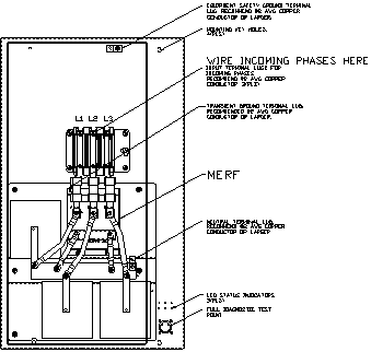
Figure 10.
MP WITH INTEGRAL FUSED DISCONNECT SWITCH
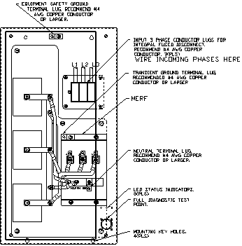
Figure 11.
DP WITH INTEGRAL FUSED DISCONNECT SWITCH
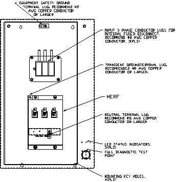
Figure 12.
SBA or DPA Surface Mount WITH INTEGRAL FUSED DISCONNECT SWITCH
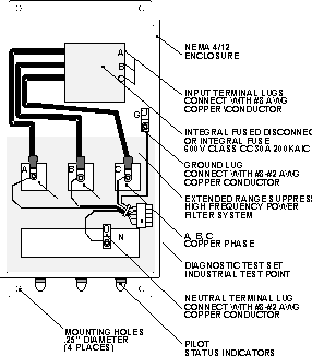
Figure 13.
BPA WITH INTEGRAL FUSED DISCONNECT SWITCH
B. UNITS WITHOUT INTEGRAL FUSED DISCONNECT SWITCH
All units without an integral fused disconnect MUST be installed via a three-pole 35 amp breaker or external fused disconnect switch with copper conductors as described in Table 2 below.
| Unit | Recommended Conductor |
| MP | #2 AWG Copper |
| DP | #4 AWG Copper |
| SBA | #8 AWG Copper |
| DPA | #8 AWG Copper |
| BPA | #8 AWG Copper |
Table 2
Recommended Installation Conductor Chart
It is recommended that Neutral and Ground conductors connecting this unit should be at least 100% of Phase conductor ampacity.
1) Wire should be stripped appropriately for inserting into lugs, and lugs should be tightened appropriately.
2) Connect three phase conductors into the lugs on the MERF box as called out in Figures 15-19 with Phase A connected to lug labeled A, Phase B connected to lug labeled B, and Phase C connected to lug labeled C.
3) Lugs should be tightened appropriately.
For single phase installations, Phase B/Lug L2 is not used.
FOR DISTRIBUTION SYSTEMS WITH A GROUND AND/OR NEUTRAL CONDUCTOR, SEE BELOW
NEUTRAL INSTALLATION: Connect neutral tap conductor to lug marked “NEUTRAL TERMINAL” as called out in Figures 15-19.
GROUND INSTALLATION: Connect ground tap conductor to green lug mounted in top center of enclosure labeled “SAFETY GROUND TERMINAL” and the copper lug mounted on the top left side of the unit’s “MERF” labeled “TRANSIENT GROUND” as called out in Figures 15-19. The ground tap conductor should be tapped from the grounding plane derived from the service entrance connection.
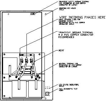
Figure 14.
MP WITHOUT INTEGRAL FUSED DISCONNECT SWITCH
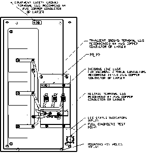
Figure 15.
DP WITHOUT INTEGRAL FUSED DISCONNECT SWITCH
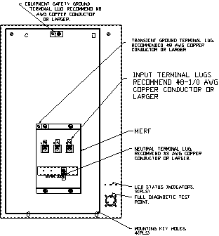
Figure 16.
SBA or DPA Surface Mount WITHOUT INTEGRAL FUSED DISCONNECT SWITCH
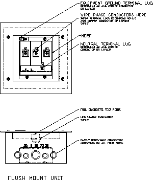
Figure 17.
DPA Flush Mount WITHOUT INTEGRAL FUSED DISCONNECT SWITCH
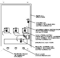
Figure 18.
BPA WITHOUT INTEGRAL FUSED DISCONNECT SWITCH
TO RESET DISTURBANCE COUNTERS
Before attempting reset of the optional disturbance counters on your Current Technology suppression filter system, the disconnect switch or circuit breaker feeding the unit should be turned to the “Off” position to remove power from the unit. In order to reset the disturbance counters to zero, the count reset connections on the disturbance counter circuit board must be momentarily connected. Refer to Figure 20 below (BPA units are not available with integral event counters. Remote Disturbance Counters (RDC) may be specified for BPA units).
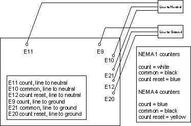
FIGURE 19.
RESET CIRCUIT FOR DISTURBANCE COUNTERS WIRING THE OPTIONAL FORM “C” DRY CONTACTS
For wiring of the form “C” dry contacts, identify the three output terminals located on the dry contact circuit board: common, normally open and normally closed. These output terminals are labeled C, NO and NC accordingly. For normally closed operation, connect the normally closed terminal and common terminal to the monitoring indicator. For normally open operation, connect the normally open terminal and common terminal to the monitoring indicator. When the status of the unit’s fuses/suppression elements changes, the NC and NO outputs reverse their status and the NC opens while the NO closes. Form “C” dry contacts are rated for 0.5 amps at 120 volts.
5. Before energizing unit, check ALL electrical connections, both field installed and factory connected, for solid electrical connection.
6. DO NOT APPLY POWER UNTIL ALL OF THE FOLLOWING ELECTRICAL FIELD CHECKS HAVE BEEN COMPLETED.
Before applying power to the unit, check off the following electrical field tests. All voltages to be measured with a TRUE RMS voltmeter (i.e., Fluke 87):
o Line-to-Line voltage does not exceed +10% of the rated nominal voltage for the unit. The unit’s rated nominal voltage can be found on the label inside the unit door or in Table 4.
o Line-to-Neutral voltage does not exceed +10% of the rated nominal voltage for the unit. The unit’s rated nominal voltage can be found on the label inside the unit door or in Table 4.
o Line-to-Ground voltage does not exceed +10% of the rated voltage for the unit as called out in Table 4.
o Neutral-to-Ground voltage does not exceed the rated voltage for the unit as called out in Table 4.
CAUTION !
VOLTAGE READINGS OTHER THAN THOSE LISTED AS ACCEPTABLE ABOVE WILL DAMAGE THE UNIT AND VOID THE WARRANTY. IF YOU HAVE QUESTIONS REGARDING VOLTAGES OR WIRING, PLEASE CALL CURRENT TECHNOLOGY.
7. FINAL INSTRUCTIONS (MP, DP, SBA, DPA surface mount and BPA):
If all voltages are within tolerance, close and latch door, and apply external power to the unit by engaging external breaker or external disconnect switch. For units with integral fused disconnect switch, turn integral fused disconnect ON. All front panel indicator lights will illuminate.
FINAL INSTRUCTION (DPA flush mount):
If all voltages are within tolerance, reconnect cable harness connector, and reattach dead front to box installed in wall. Apply external power to unit by engaging external breaker or external disconnect switch. Front panel indicator lights will illuminate.
OPERATIONS
1. The suppression filter system is now operational. Current Technology suppression filter systems are designed to operate indefinitely without any component failures or routine parts replacement.
2. To disengage unit and remove protection from the electrical system, either turn off external power by disengaging the circuit breaker or external fused disconnect switch feeding power to the unit; or, for units with integral fused disconnect switch, turn switch to OFF position.
3. Should verification and test of unit operation be necessary, the integral test point installed in each Current Technology unit allows connection of Current Technology’s DTS-2 portable Diagnostic Test Set to test component and total unit function*. See Maintenance Section and DTS-2 product literature for further information.
(* BPA unit require DTS-2 adapter for DTS-2 Diagnostic Test Set connection.)
MAINTENANCE
Your Current Technology suppression filter system does not require periodic maintenance. The unit’s heavy-duty design should preclude the need for any repairs; however, the following indicators may signal the need for fuse or indicator light replacement and/or unit testing:
UNITS WITH INTEGRAL FUSED DISCONNECT
| INDICATION | PROCEDURE |
| One or more phase indicator lights are off. |
1. Check that the external power source supplying power to unit is energized. 3. Check that fuses are installed and operational. 4. Check connector connecting indicator lights to light board. 5. If all of above are O.K., contact factory. 6. If internal fuse or external breaker are faulty/tripped, use DTS-2 portable diagnostic test set to verify unit integrity before fuse replacement and/or breaker reclosing. |
| Portable Diagnostic Test Set (Current Technology Model DTS-2) Indications | Refer to Diagnostic Test Set Manual for procedures and explanations. |
FUSES: Recommended fuses for use with Current Technology suppression filter systems are as follows:
| Unit | Recommended Integral Disconnect Fuse |
| MP | 35 Amp 200,000 AIC Class J-type |
| DP | 35 Amp 200,000 AIC Class J-type |
| SBA | 30 Amp 200,000 AIC Class J-type |
| DPA | 30 Amp 200,000 AIC Class J-type |
| BPA | 15 Amp 200,000 AIC Class CC-type |
Table 3
Recommended Fuses
UNITS WITHOUT INTEGRAL FUSED DISCONNECT
| INDICATION | PROCEDURE |
| One or more phase indicator lights are off. |
1. Check that the circuit breaker/external disconnect switch supplying power to unit is energized. 3. If all of above are O.K., contact Factory. 4. If external disconnect switch fuses or external breaker are faulty/tripped, use DTS-2 portable diagnostic test set to verify unit integrity before fuse replacement and/or breaker reclosing. |
| Portable Diagnostic Test Set (Current Technology Model DTS-2) Indications | Refer to Diagnostic Test Set Manual for procedures and explanations. |
TABLE 4 : NOMINAL VOLTAGES
| MODEL3 | VOLTAGE | CONFIGURATION | NOMINAL VOLTAGES | |||
| SUFFIX | L – L1 | L – N1 | L – G1 | N – G | ||
| 120/240-2G-DF | 120/240 | GROUNDED NEUTRAL | 240 | 120 | 120 | 0 – 2 |
| 120/208-3GY-DF | 120/208 | GROUNDED WYE | 208 | 120 | 120 | 0 – 2 |
| 220/380-3GY-DF | 220/380 | GROUNDED WYE | 380 | 220 | 220 | 0 – 2 |
| 277/480-3GY-DF | 277/480 | GROUNDED WYE | 480 | 277 | 277 | 0 – 2 |
| 347/600-3GY-DF | 347/600 | GROUNDED WYE | 600 | 347 | 347 | 0 – 2 |
| 120/240-3GHD-DF | 120/240 X 208 | GROUNDED NEUTRAL “HIGH-LEG” DELTA | 240 | A&C: 120 B: 208 | A&C: 120 B: 208 | 0 – 2 |
| 240-3GCD-DF | 240 | GROUNDED CORNER DELTA | 240 | 0/2402 | ||
| 240-3UD-DF | 240 | UNGROUNDED DELTA | 240 | |||
| 480-3GCD-DF | 480 | GROUNDED CORNER DELTA | 480 | 0/4802 | ||
| 480-3UD | 480 | UNGROUNDED DELTA | 480 | |||
| 575-3GCD-DF | 575 | GROUNDED CORNER DELTA | 575 | 0/5752 | ||
| 575-3UD-DF | 575 | UNGROUNDED DELTA | 575 | |||
| 600-3GCD-DF | 600 | GROUNDED CORNER DELTA | 600 | 0/6002 | ||
| 600-3UD-DF | 600 | UNGROUNDED DELTA | 600 | |||
1NOTE: All line voltages should be within +/- 10% of rated nominal voltage.
2NOTE: For delta systems, phase-to-ground voltages is either 1) The rated phase-to-phase voltage or 2) Zero (0) for the “grounded” phase.
3NOTE: Model prefix would specify MP, DP, SBA, DPA or BPA. DF suffix on the model number designates unit with integral fused disconnect switch. Nominal voltage ratings remain the same with or without integral fused disconnect.
4NOTE: Neutral-Ground voltages will vary per installation.
FIVE YEAR LIMITED WARRANTY
The Warranty Card must be completely filled out and returned to the factory to initiate Current Technology’s Five Year Limited Warranty and Five Year Field Check Program.
LEGAL NOTICE
Current Technology products are protected by patents which may be issued after the publication of this document as well as by one or more of the following patents: 5,023,746; 4,835,650; 4,675,538; 4,675.772; 5,191,502; 4,860,502; 4,127,888; 5,146,357; 4,794,490; 5,257,157. All rights reserved. Current Technology will enforce and protect its patent rights as provided by Section 35 USC and a $500,000 litigation protection insurance policy.
APPENDIX I
Table No. Description Page
1. Recommended Installation Wiring 6
2. Recommended Conductors for Units with Integral 9
Fused Disconnect
3. Recommended Disconnect Fuses 14
4. Nominal Unit Voltages 15
APPENDIX II
Figure No. Description Page
1. MP Conduit Entrance Location 3
2. DP Conduit Entrance Location 3
3. SBA and Surface Mount DPA Conduit Entrance Location 4
4. DPA Flush Mount Conduit Entrance Location 4
5. BPA Conduit Entrance 4
6. MP Mounting Template Drawing 5
7. DP Mounting Template Drawing 5
8. SBA and Surface Mount DPA Mounting Template Drawing 5
9. BPA Mounting Template Drawing 5
10. MP with Integral Fused Disconnect Switch 7
11. DP with Integral Fused Disconnect Switch 7
12. SBA or DPA with Integral Fused Disconnect Switch 8
13. BPA with Integral Fused Disconnect Switch 8
14. MP without Integral Fused Disconnect Switch 9
15. DP without Integral Fused Disconnect Switch 10
16. SBA or DPA without Integral Fused Disconnect Switch 10
17. DPA Flush-mount 11
18. BPA without Integral Fused Disconnect Switch 11
19. Reset Ciruict for Disturbance Counters 12